
Multi-Axis FDM 3D printing.
We developed a fixture-based workflow for printing parts in several orientations on a conventional three-axis FDM printer. We then studied the accuracy of different mounting solutions and the compatibility of different materials.
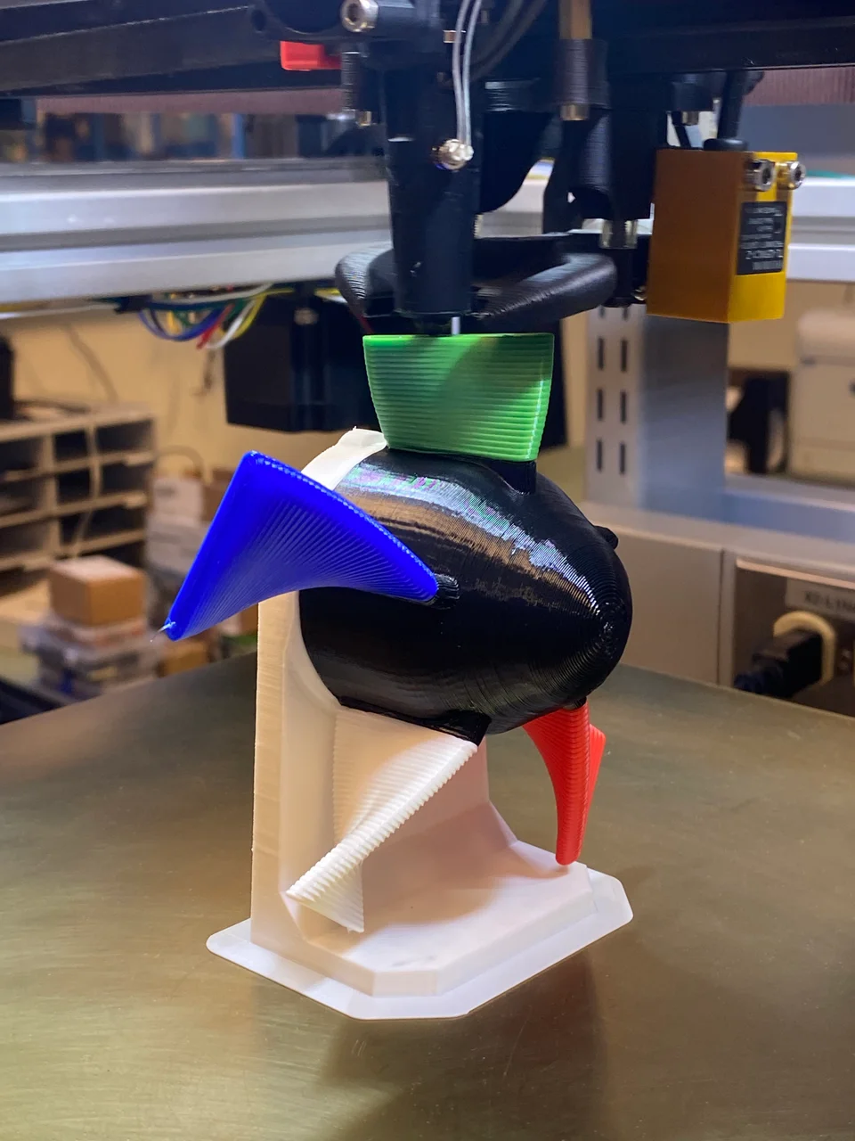
On this page01Overview
Changing the build direction with a printed fixture.
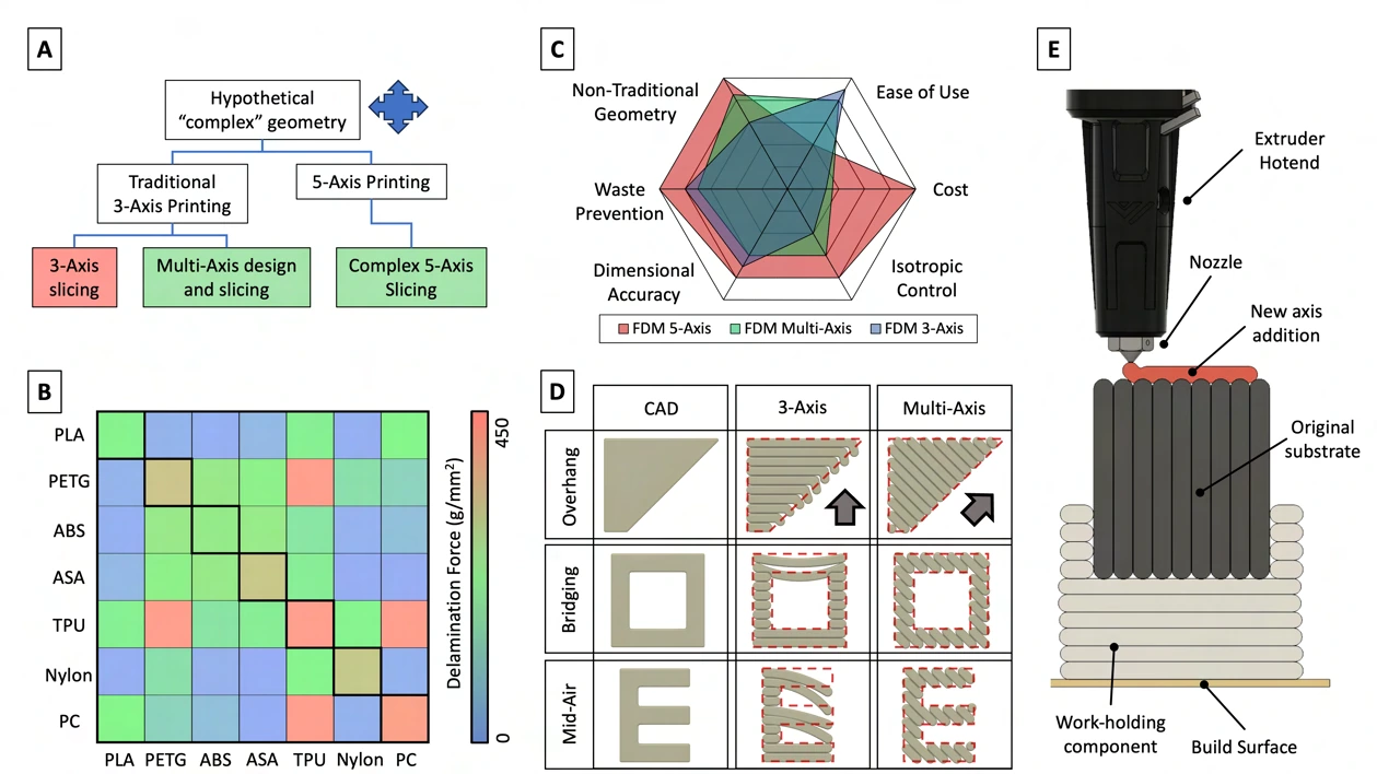
A conventional FDM printer deposits each layer along one fixed build direction. This keeps the machine and slicing workflow simple, but it can leave steep surfaces stair-stepped, make some geometry depend on support material, and place weak layer interfaces across a part’s load path.[1]
This study presents a sequential way to vary that direction without adding rotary machine axes or replacing the slicer. The printer first makes a base part and a matching work-holding fixture. After the base is removed and mounted in the fixture, the printer can locate it in its original coordinate frame and deposit the next features from a new direction. The method trades continuous multi-axis motion for planned reorientation between ordinary print steps.[1]
- reported single-cube dimensional range
- 100–200 µm
Reported for single cubes; larger assembled geometries showed greater dimensional error.[1]
- lowest variability among tested holders
- 90 µm
The bolted fixture showed the lowest variability in the holder comparison. This measures variation between results, rather than absolute dimensional accuracy.[1]
- rotated turbine demonstration
- 5 blades · 72° steps
Blade thickness was within 50 µm of design; radius and tip-length errors were around 300 µm.[1]
The printer becomes its own positioning reference.
The work is planned as a sequence of labelled STL components. Each component is sliced separately in Cura, printed in the planned orientation, and assembled between print steps. Because the printer made both the substrate and fixture, its coordinate system serves as the reference for placing later material. The fixture is therefore both a holder and a locating feature in the fabrication plan.[1]
The demonstrations used a custom HevORT printer with a Goliath long-melt-zone hot end and PLA. This setup kept the toolpath workflow close to common desktop FDM practice while requiring deliberate design of the fixture, contact points, rotation steps, and nozzle clearance.[1]
A sequence of prints, one coordinate frame
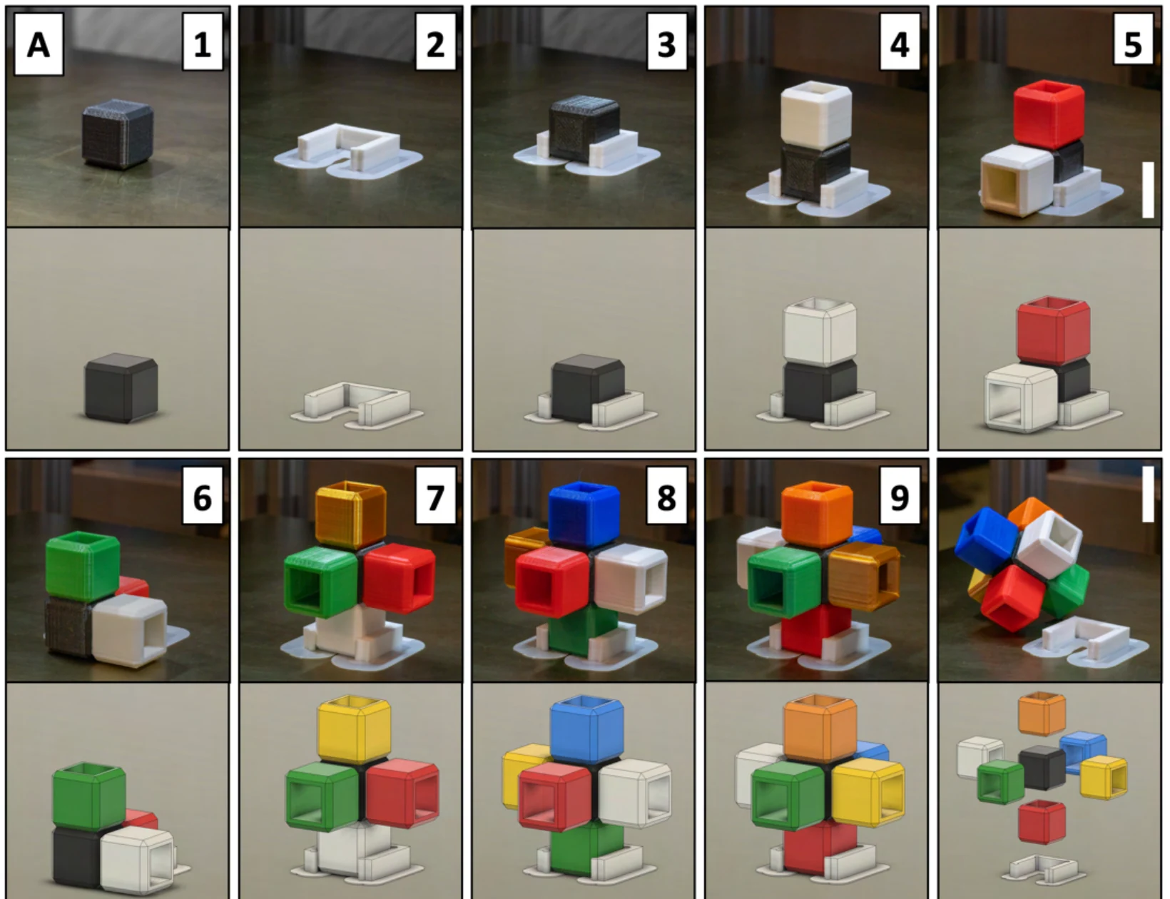
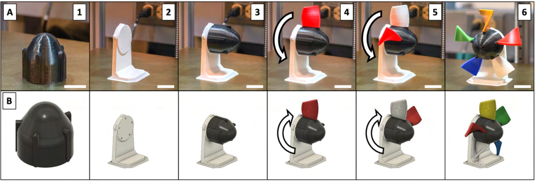
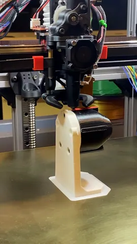
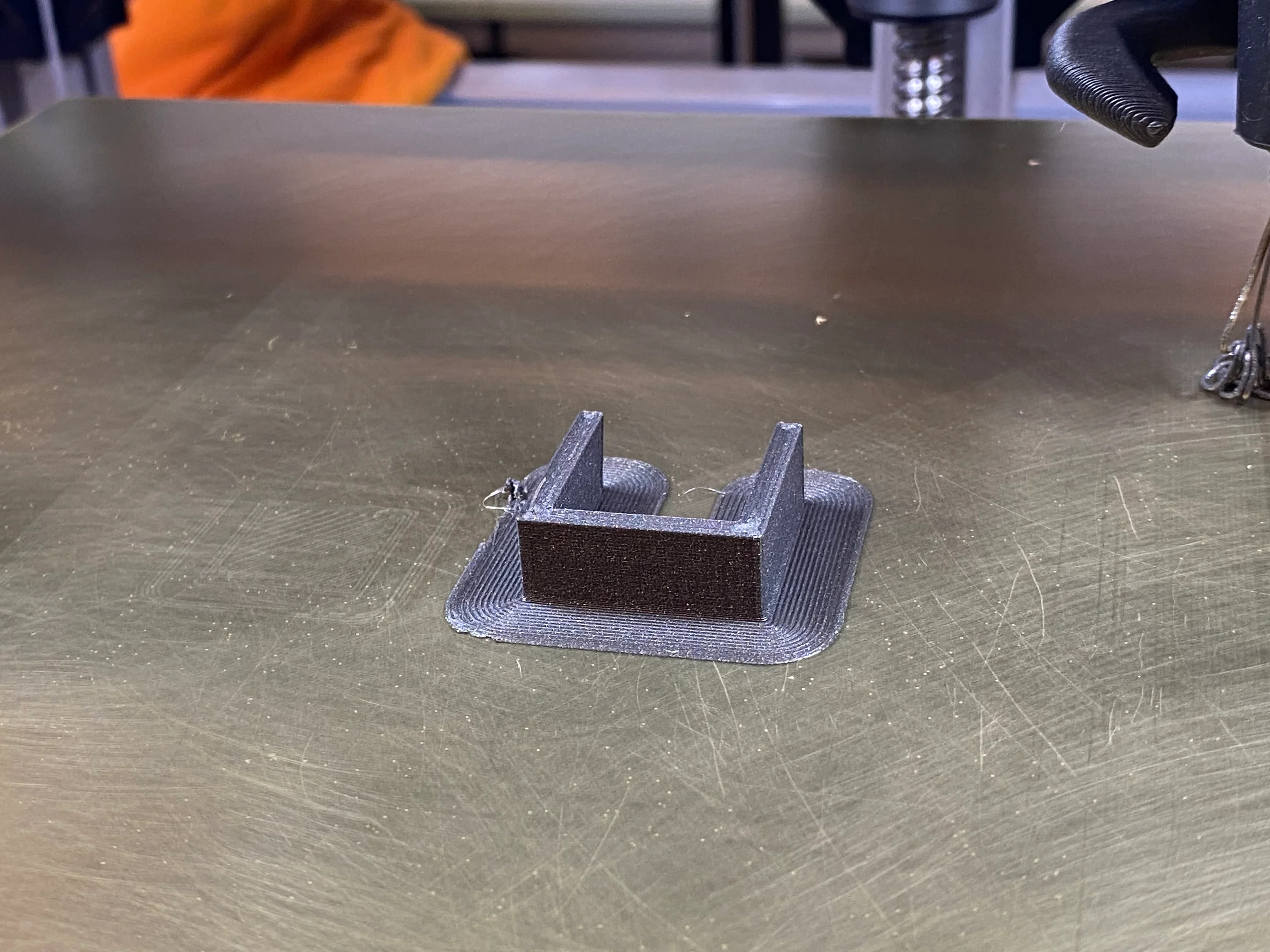
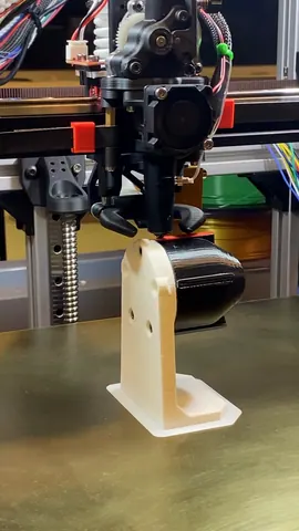
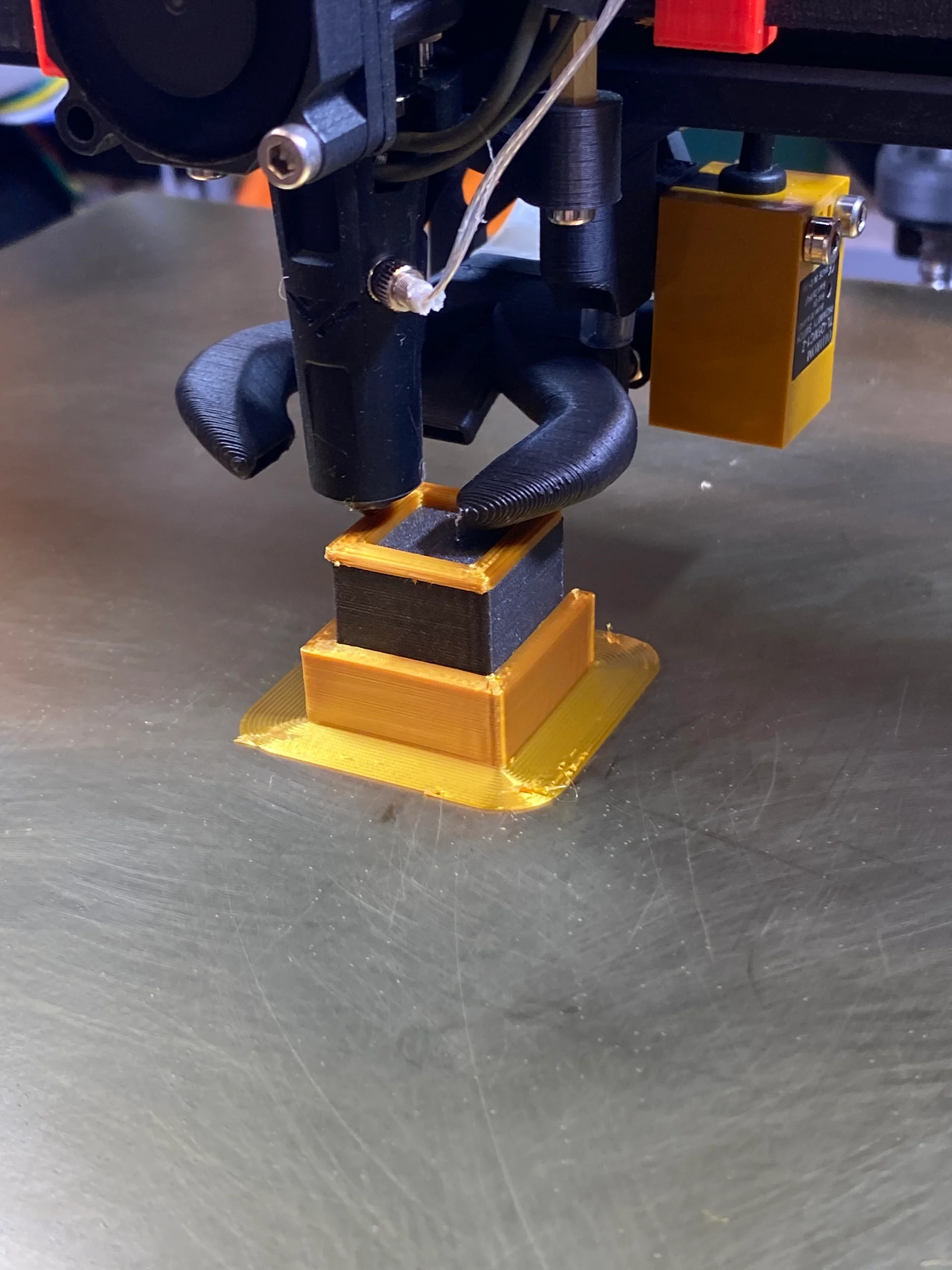
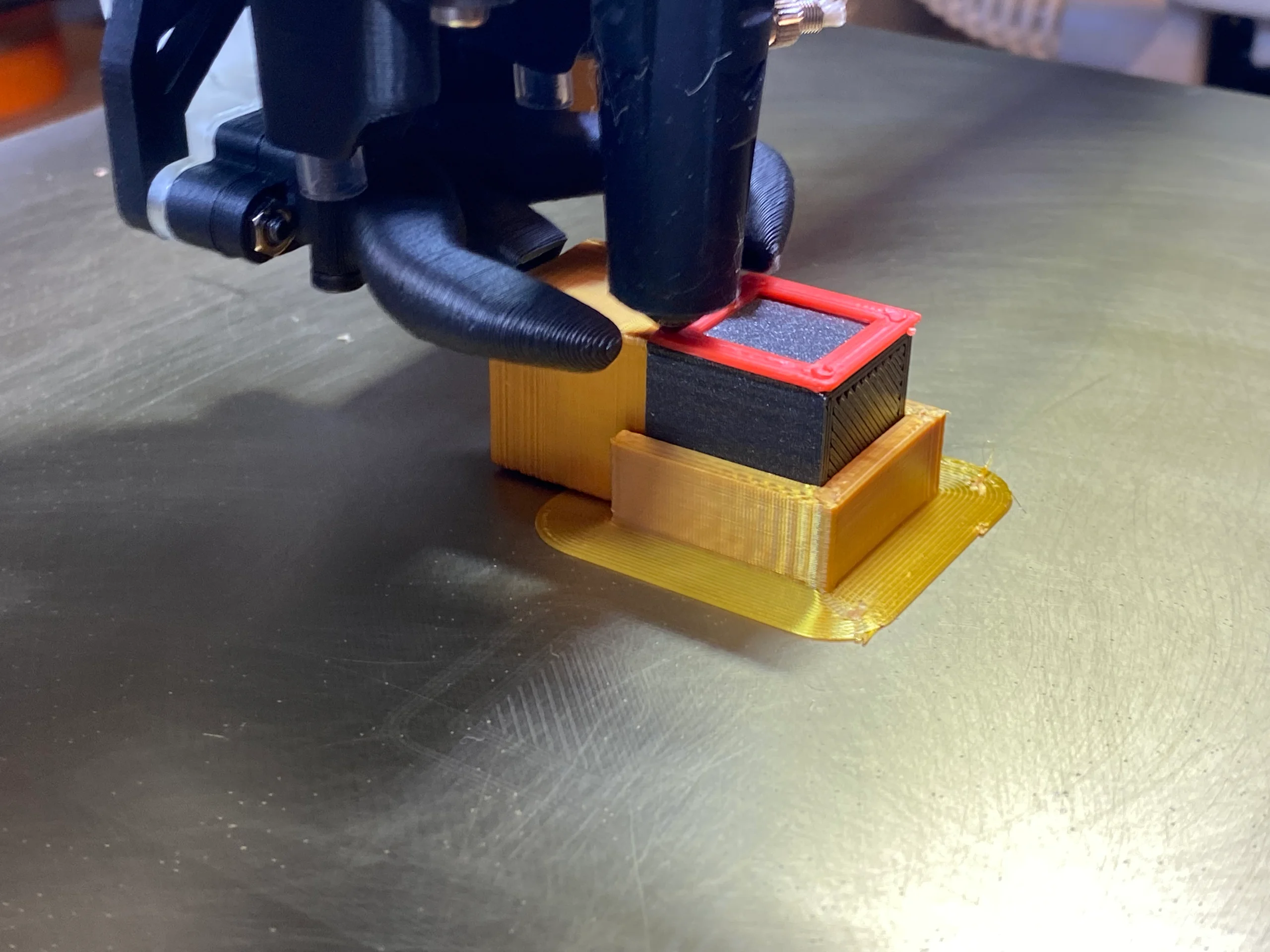
The first demonstration is a multi-sided cube assembly that would otherwise need support material or a compromise in its geometry. A dark substrate is printed, a white holder is printed to locate it, and successive coloured cubes are added as the assembly is repositioned. The sequence shows the physical prints alongside CAD views, making the planned order and changing deposition directions visible.[1]
This is a discrete workflow: the printer does not rotate a part during extrusion. The operator follows pre-planned steps, and the holder preserves the relationship between the mounted part and the printer’s original coordinates.[1]
The holder sets the tolerance ceiling
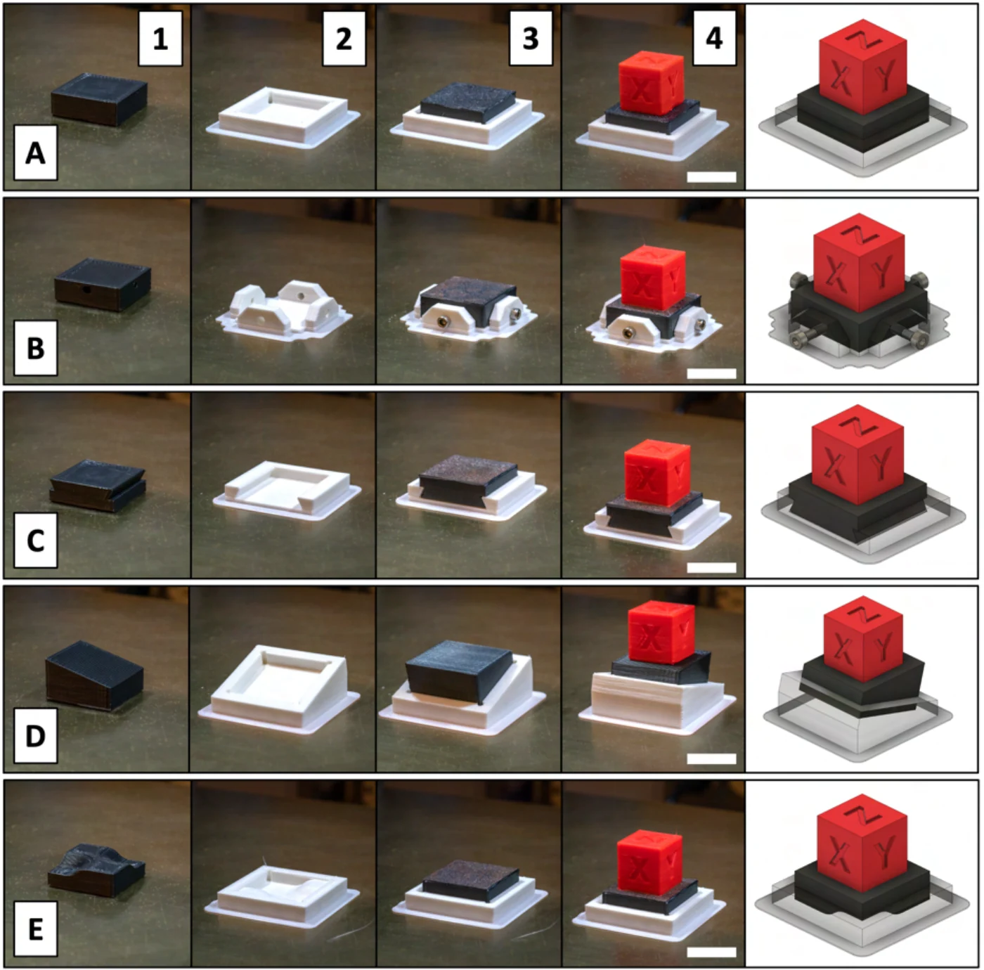
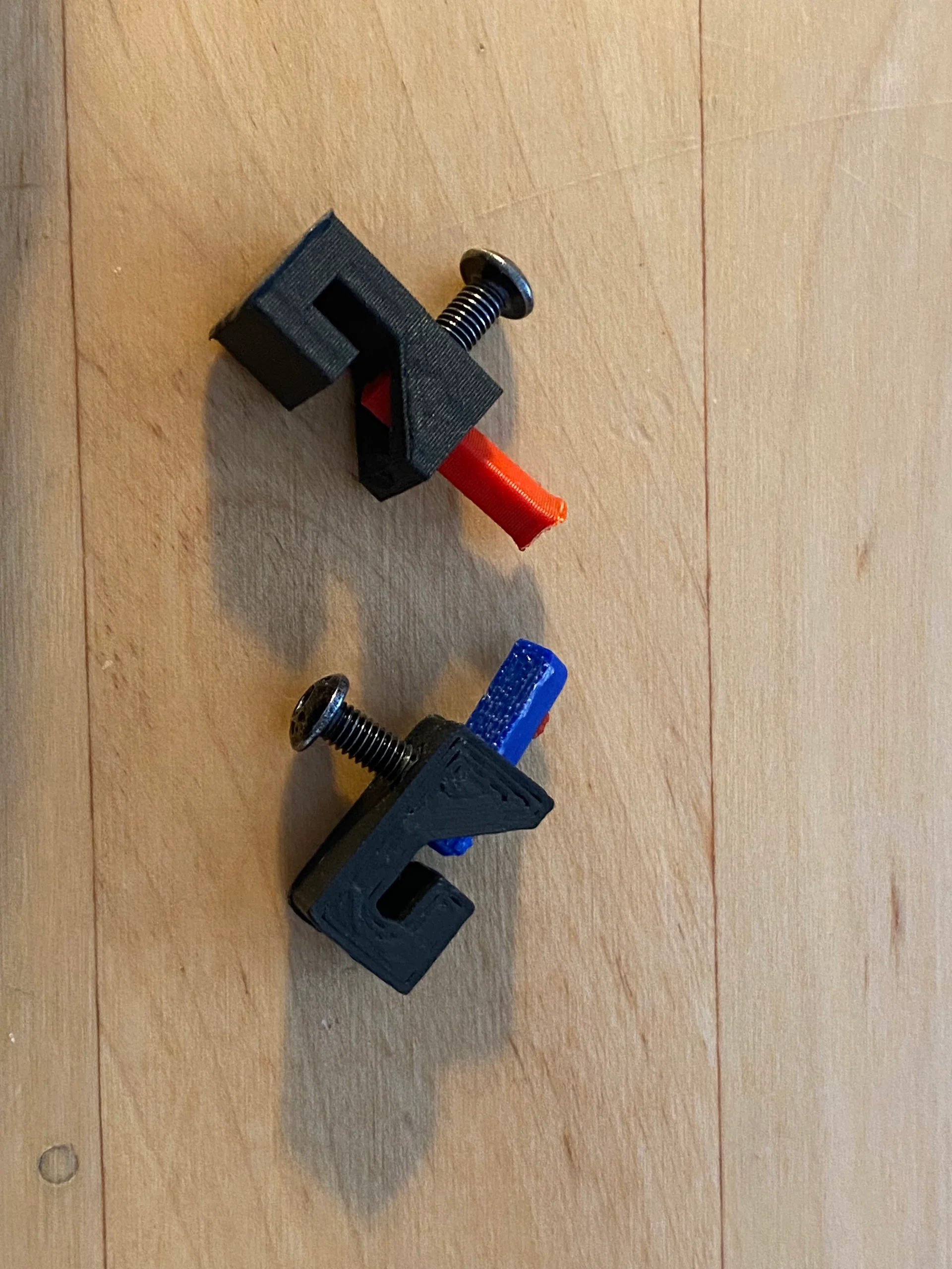
The cube trial exposed a practical weakness: as later features were printed farther from the mounting point, the assembly could flex. The paper compares friction-fit, bolted, dovetail, angled, and conformal holders to find a more stable reference. Bolting through alignment holes had the lowest reported variability at 90 µm; friction showed variability centred around 240 µm. The paper describes the bolted approach as the strongest candidate for larger builds.[1]
This comparison makes work-holding a core part of the process design. A print direction can only be useful when the reoriented part stays located under nozzle contact and when the planned toolpath clears both the fixture and the machine.[1]
Rotating the work for a turbine blade
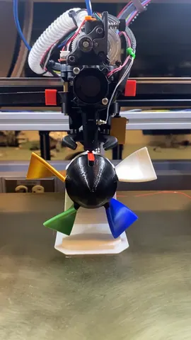
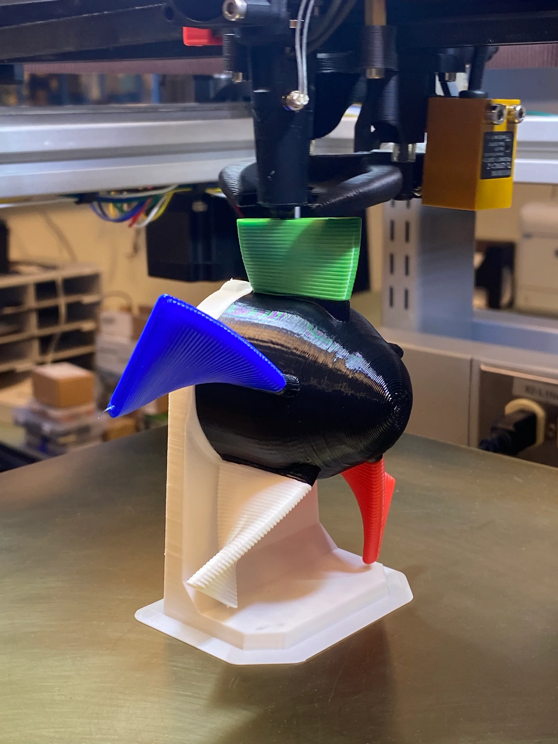
The turbine demonstration uses heat-set inserts in a more elaborate holder to index a central core as five blades are printed. The part advances by 72 degrees between blade steps. The reported blade thickness was within 50 µm of the design, while blade radius and tip length had errors on the order of 300 µm.[1]
A nozzle collision detached the holder during the reported run. Since the machine coordinate reference remained available, the holder was reprinted, the substrate remounted, and printing resumed. This recovery illustrates a useful property of the method, while the collision also shows why clearance planning remains important as fixtures and parts become more complex.[1]
Extending the method across materials
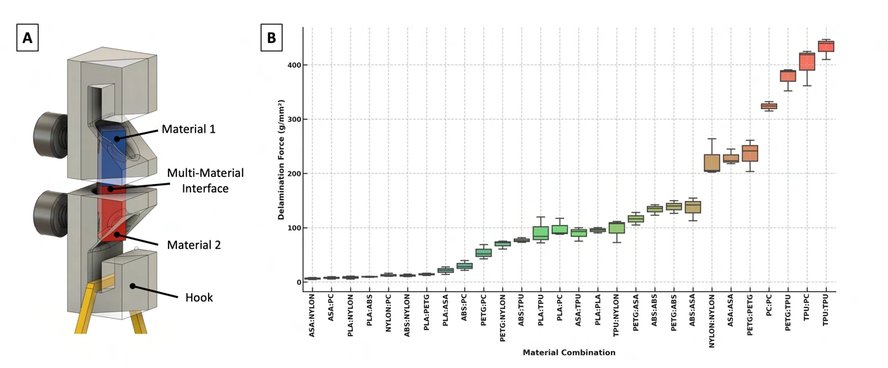
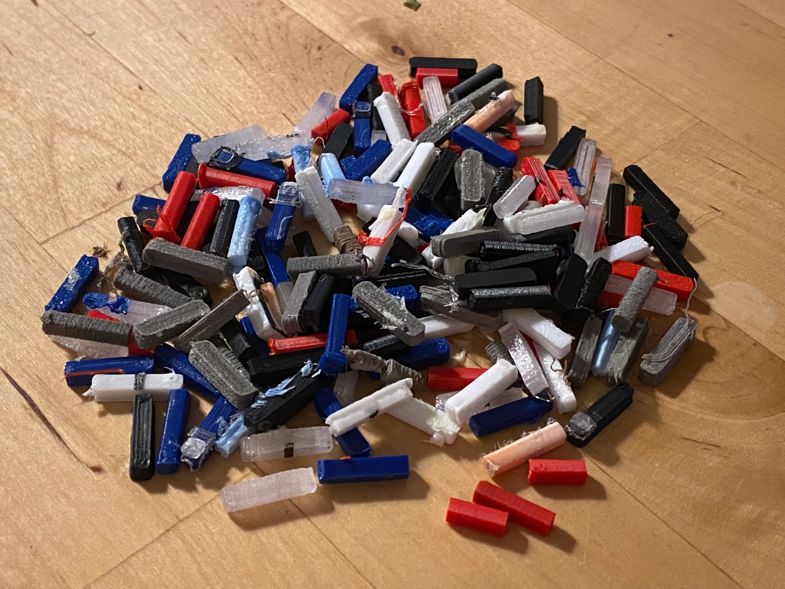
The manuscript also tests interfaces between common FDM polymers. Samples were printed vertically to emphasize delamination, then pulled apart; the paper reports three specimens per material pairing. It identifies several strong candidate pairings, including TPU with itself, polycarbonate with itself, TPU with polycarbonate, and TPU with PETG.[1]
The material screen used three specimens per pairing and a limited set of print settings. It provides candidate interfaces for further testing; the measured rankings depend on the printing conditions and the geometry of the specimens.[1]
The complete project archive.
Scroll or swipe to explore. Select a photo to enlarge it, or a play-marked video to watch.
Research & figure sources.
- [1] Morocz, Yonatan. Multi-Axis FDM 3D Printing. EngrXiv preprint, version 1, posted September 5, 2025. DOI: 10.31224/5307. CC BY 4.0.
Primary source for the method, printer and slicer workflow, cube and turbine demonstrations, dimensional measurements, holder comparison, and polymer-interface experiment. Figure crops are reproduced under the record’s CC BY 4.0 license.
Figures: Figure 1, PDF page 3; complete embedded figure, panels A through E; Figure 2, PDF page 4; full panel crop, including 20 mm scale bar; Figure 5, PDF page 6; full panel crop; Figure 6, PDF page 7; full panel crop; Figure 9, PDF page 11; complete embedded figure, panels A and B.