
Brain clearing chamber.
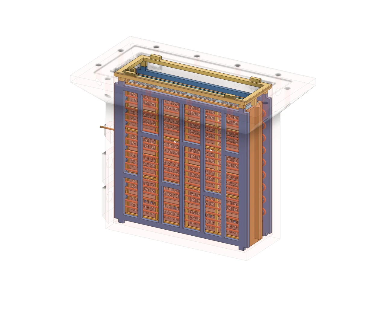
A modular tissue-clearing chamber with removable electrode racks, side ports, and a supported printed basin.
On this page01Overview
A compact chamber for a complete batch.
I designed this version of the BCC brain clearing chamber based on a previous design by Daniel Krykhtin and Hannah Derue. It holds 24 mouse brains in individual baskets, arranged four across and six rows high, and is intended for circulating electrophoretic clearing and antibody incubation before light-sheet microscopy.
The cassette layout brings the baskets and opposing electrode panels into a removable assembly. The current design, revision 8, adds four side openings and a matching support beneath the basin flange.
- Design capacity
- 24 baskets
- Sample layout
- 4 × 6
- Current stage
- CAD prototype
One carrier. Twenty-four individual baskets.
A U-frame, seven separate trays, and a removable front grid form the basket carrier. The baskets sit between two electrode panels; each panel supports a serpentine wire on a flat backing grid. These modules lift out of the basin for access.
Separating the shelves from the frame lets the trays print flat instead of stacking suspended roofs into one tall printed part.


A replaceable seal beneath a flat lid.
The closure combines a 5 mm laser-cut acrylic lid, a continuous molded PDMS gasket, and a printed top clamp. Twelve bolts connect the closure to heat-set inserts in the external PLA backing ring.
The gasket has a designed free thickness of 2 mm and sits in a locating recess in the basin. Its separate printed mold has a 4 mm-deep cavity. Gasket compression and sealing still need physical testing.


Follow the basin’s slope all the way to the flange.
Revision 8 fills the gap beneath the basin’s 45-degree taper with a separate conformal PLA saddle. It sits on the lower backing ring and extends the matching contact surface up to the flange.
The two-piece arrangement keeps the insert pockets accessible on a flat surface. The ring and saddle are designed to slide upward around the basin, with notches clearing the side-port pads. The matching CAD surfaces establish the intended fit; clamp deflection and physical seating remain to be tested.


Keep four openings on one narrow face.
Two fluid openings sit low on the same end wall, with one lead opening for each electrode above them. Sloping pads support the openings without intruding into the internal guide grooves.
The current 6 mm fluid bores are layout placeholders awaiting the final fittings. The smaller wire bores and modeled lead pins are also provisional; adhesive seals, connectors, and internal electrode jumpers have not yet been selected.

Split the design around how its parts are made.
The basin, baskets, carrier, and electrode frames are intended for resin printing. External clamps, the backing pieces, and the gasket mold are intended for PLA printing; the lid uses a flat acrylic sheet. The flat rack layout and sloping basin geometry are designed around print orientation and access.
Fourteen fabrication meshes have passed geometric checks for closed, connected solids. The assembly has also been reviewed for interference and sampled removal positions. These are CAD checks: printing, material compatibility, leakage, and tissue-processing performance remain unvalidated.


From the first layout to the final assembly.
The complete 90-second film follows the chamber through its design revisions, from sample packing and basket supports to the gasket, lid, side connections, and final assembly.
Inside revision 8.


Scroll or swipe to explore. Select a render to enlarge it.
Explore the chamber in parts.
Rotate revision 8, separate its components, or move a cross section through the basin and removable internals.
View all assembliesLoad the model to explore its parts.
3.4 MBDrag to orbit; scroll or pinch to zoom. In Cross section mode, the slider moves the shaded, hatched cut through the model. In Explode mode, it separates or assembles the parts. Select a part to change its appearance or hide it. With the viewer focused, arrow keys rotate, + / − zoom, and R resets.
Building on the CLARITY workflow.
The project brief uses the electrophoretic chamber in the Advanced CLARITY protocol as a design reference. The BCC geometry and renders shown here document a separate chamber prototype.
Tomer, R., Ye, L., Hsueh, B. & Deisseroth, K. Advanced CLARITY for rapid and high-resolution imaging of intact tissues. Nature Protocols 9, 1682–1697 (2014). DOI: 10.1038/nprot.2014.123.